
14×24 Workshop Plans
This 14×24 workshop sits on a 4″ concrete slab, with 9′ walls, a 6/12 gable roof and a peak of 12′ 10-7/8″. The 74″-wide double door opening gets a doubled header sized for the roof load above it. Rafters are 2x4 at 16″ on center. All 177 pieces of lumber are lettered below with their lengths and cuts, and the shopping list comes to 147 boards plus sheet goods and hardware.
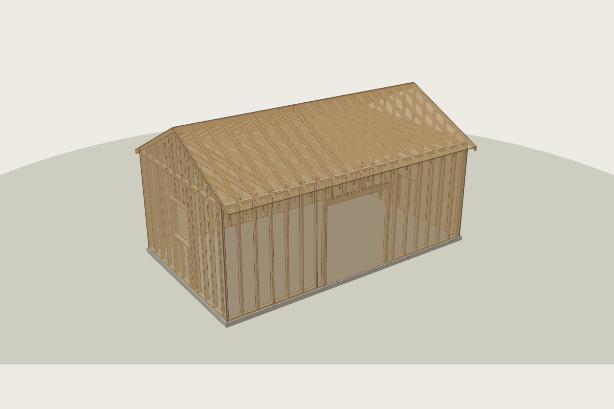
Shopping list
Short pieces are cut from the offcuts of longer boards. Buy one spare of each size.
Parts and cut list
Cut every part, then pencil its letter on it. The steps call parts by letter.
| Part | Qty | Size | Length | Piece | How to cut |
|---|---|---|---|---|---|
| A | 2 | 2x6 | 77" | Header ply | square; two plies with a 1/2" plywood spacer |
| B | 1 | 2x4 | 284-1/2" | Top plate | square ends; laps the next piece at the corner |
| C | 1 | PT 2x4 | 107" | Bottom plate | square ends; laps the next piece at the corner |
| D | 14 | 2x4 | 104-5/8" | Stud | square both ends |
| E | 2 | 2x4 | 104-5/8" | King stud | square both ends |
| F | 1 | PT 2x4 | 103-1/2" | Bottom plate | square ends; laps the next piece at the corner |
| G | 2 | 2x4 | 81" | Jack stud | square both ends |
| H | 5 | 2x4 | 18-1/8" | Cripple | square both ends |
| J | 2 | 2x6 | 39-1/2" | Header ply | square; two plies with a 1/2" plywood spacer |
| K | 1 | PT 2x4 | 164-1/2" | Bottom plate | square ends; laps the next piece at the corner |
| L | 1 | 2x4 | 164-1/2" | Top plate | square ends; laps the next piece at the corner |
| M | 9 | 2x4 | 104-5/8" | Stud | square both ends |
| N | 2 | 2x4 | 104-5/8" | King stud | square both ends |
| P | 2 | 2x4 | 79" | Jack stud | square both ends |
| Q | 4 | 2x4 | 41" | Cripple | square both ends |
| R | 1 | 2x4 | 36-1/2" | Rough sill | square both ends |
| S | 2 | 2x4 | 20-1/8" | Cripple | square both ends |
| T | 1 | PT 2x4 | 284-1/2" | Bottom plate | square ends; laps the next piece at the corner |
| U | 1 | 2x4 | 284-1/2" | Top plate | square ends; laps the next piece at the corner |
| V | 19 | 2x4 | 104-5/8" | Stud | square both ends |
| W | 2 | 2x6 | 39-1/2" | Header ply | square; two plies with a 1/2" plywood spacer |
| X | 1 | PT 2x4 | 164-1/2" | Bottom plate | square ends; laps the next piece at the corner |
| Y | 1 | 2x4 | 164-1/2" | Top plate | square ends; laps the next piece at the corner |
| Z | 9 | 2x4 | 104-5/8" | Stud | square both ends |
| AA | 2 | 2x4 | 104-5/8" | King stud | square both ends |
| AB | 2 | 2x4 | 79" | Jack stud | square both ends |
| AC | 4 | 2x4 | 41" | Cripple | square both ends |
| AD | 1 | 2x4 | 36-1/2" | Rough sill | square both ends |
| AE | 2 | 2x4 | 20-1/8" | Cripple | square both ends |
| AF | 2 | 2x4 | 284-1/2" | Cap plate | laps over the next wall at the corner |
| AG | 2 | 2x4 | 164-1/2" | Cap plate | laps over the next wall at the corner |
| AH | 1 | 2x6 | 288" | Ridge board | square both ends |
| AJ | 38 | 2x4 | 108-1/4" | Common rafter | plumb cut 6/12 at the ridge; birdsmouth seat 1-1/2", heel 3/4"; tail plumb cut 12" past the wall |
| AK | 17 | 2x6 | 168" | Rafter tie | top corners cut to 6/12 |
| AL | 2 | 2x4 | 39-5/8" | Gable stud | top cut 6/12 (26.6°), long point up |
| AM | 2 | 2x4 | 35-5/8" | Gable stud | top cut 6/12 (26.6°), long point up |
| AN | 2 | 2x4 | 31-5/8" | Gable stud | top cut 6/12 (26.6°), long point up |
| AP | 2 | 2x4 | 27-5/8" | Gable stud | top cut 6/12 (26.6°), long point up |
| AQ | 2 | 2x4 | 23-5/8" | Gable stud | top cut 6/12 (26.6°), long point up |
| AR | 2 | 2x4 | 19-5/8" | Gable stud | top cut 6/12 (26.6°), long point up |
| AS | 2 | 2x4 | 15-5/8" | Gable stud | top cut 6/12 (26.6°), long point up |
| AT | 2 | 2x4 | 11-5/8" | Gable stud | top cut 6/12 (26.6°), long point up |
| AU | 2 | 2x4 | 7-5/8" | Gable stud | top cut 6/12 (26.6°), long point up |
| AV | 2 | 2x4 | 3-5/8" | Gable stud | top cut 6/12 (26.6°), long point up |
Step by step
New pieces are in colour with their letters. Work already done is greyed out. Open it in the builder to turn the model and print the manual.
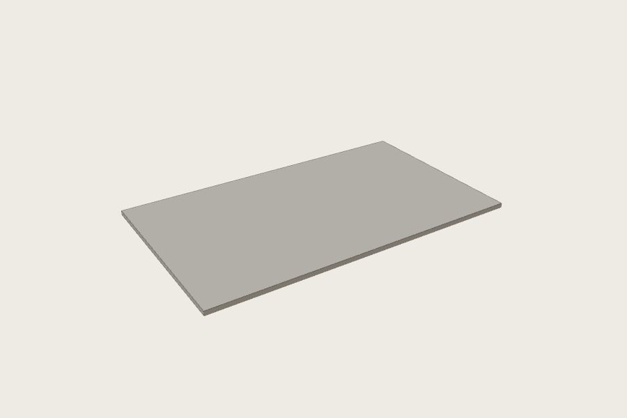
Pour the slab
- Form, gravel, pour a 4" slab with a thickened edge.
- Anchor bolts 6" from every plate end and every 6 ft.
floatlevel
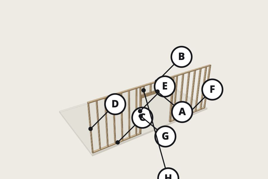
Build the front wall
A ×2 2x6 77"B ×1 2x4 284-1/2"C ×1 2x4 107"D ×14 2x4 104-5/8"E ×2 2x4 104-5/8"F ×1 2x4 103-1/2"G ×2 2x4 81"H ×5 2x4 18-1/8"
- Lay bottom and top plates side by side on the floor.
- Mark stud left edges from the left end (outside view): 0" · 15-1/4" · 31-1/4" · 47-1/4" · 63-1/4" · 79-1/4" · 95-1/4" · 111-1/4" · 127-1/4" · 143-1/4" · 159-1/4" · 175-1/4" · 191-1/4" · 207-1/4" · 223-1/4" · 239-1/4" · 255-1/4" · 271-1/4" · 283"
- Frame the 74" × 82-1/2" door: kings, jacks, header.
- Nail 2 × 16d through the plates into each stud end.
- Equal diagonals, stand it up, plumb, brace.
sawhammerlevelsquare
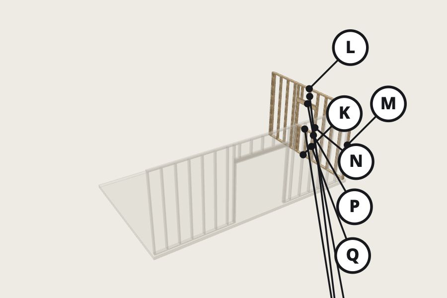
Build the right wall
J ×2 2x6 39-1/2"K ×1 2x4 164-1/2"L ×1 2x4 164-1/2"M ×9 2x4 104-5/8"N ×2 2x4 104-5/8"P ×2 2x4 79"Q ×4 2x4 41"R ×1 2x4 36-1/2"S ×2 2x4 20-1/8"
- Lay bottom and top plates side by side on the floor.
- Mark stud left edges from the left end (outside view): 0" · 15-1/4" · 31-1/4" · 47-1/4" · 63-1/4" · 79-1/4" · 95-1/4" · 111-1/4" · 127-1/4" · 143-1/4" · 159-1/4" · 163"
- Frame the 36-1/2" × 36-1/2" window: kings, jacks, header.
- Nail 2 × 16d through the plates into each stud end.
- Equal diagonals, stand it up, plumb, brace.
sawhammerlevelsquare
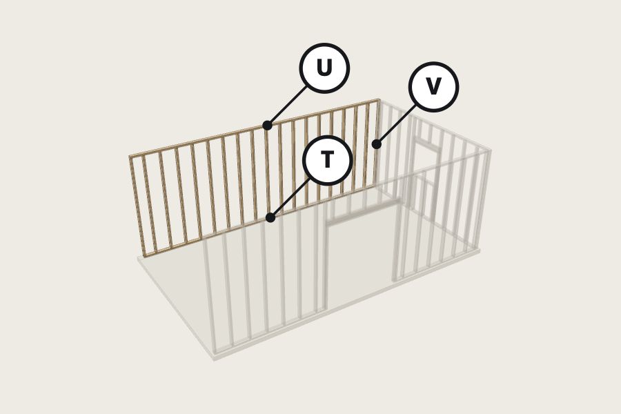
Build the back wall
T ×1 2x4 284-1/2"U ×1 2x4 284-1/2"V ×19 2x4 104-5/8"
- Lay bottom and top plates side by side on the floor.
- Mark stud left edges from the left end (outside view): 0" · 15-1/4" · 31-1/4" · 47-1/4" · 63-1/4" · 79-1/4" · 95-1/4" · 111-1/4" · 127-1/4" · 143-1/4" · 159-1/4" · 175-1/4" · 191-1/4" · 207-1/4" · 223-1/4" · 239-1/4" · 255-1/4" · 271-1/4" · 283"
- Nail 2 × 16d through the plates into each stud end.
- Equal diagonals, stand it up, plumb, brace.
sawhammerlevelsquare
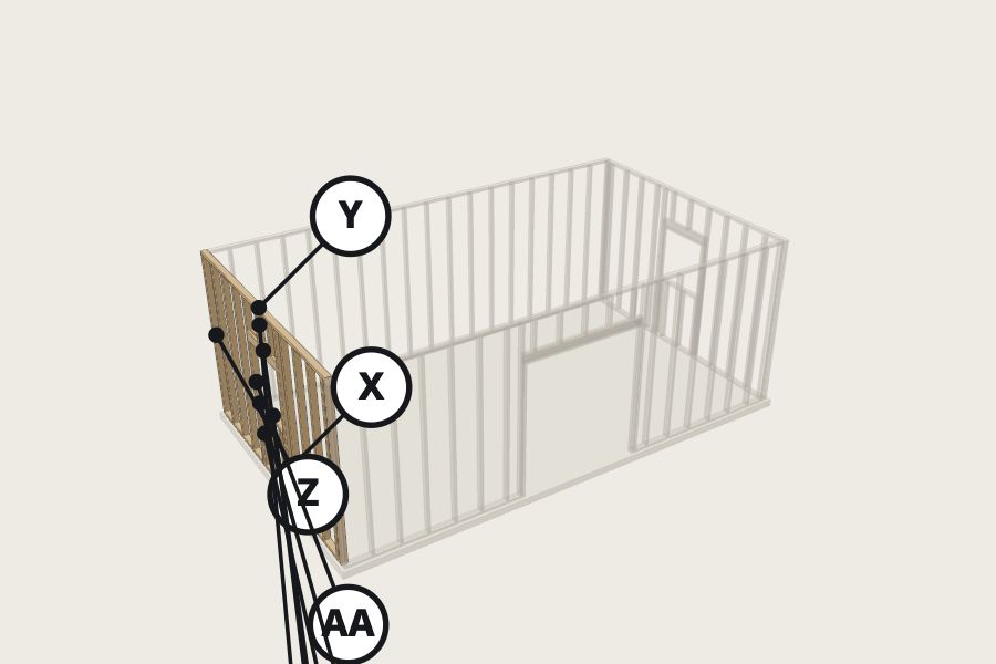
Build the left wall
W ×2 2x6 39-1/2"X ×1 2x4 164-1/2"Y ×1 2x4 164-1/2"Z ×9 2x4 104-5/8"AA ×2 2x4 104-5/8"AB ×2 2x4 79"AC ×4 2x4 41"AD ×1 2x4 36-1/2"AE ×2 2x4 20-1/8"
- Lay bottom and top plates side by side on the floor.
- Mark stud left edges from the left end (outside view): 0" · 15-1/4" · 31-1/4" · 47-1/4" · 63-1/4" · 79-1/4" · 95-1/4" · 111-1/4" · 127-1/4" · 143-1/4" · 159-1/4" · 163"
- Frame the 36-1/2" × 36-1/2" window: kings, jacks, header.
- Nail 2 × 16d through the plates into each stud end.
- Equal diagonals, stand it up, plumb, brace.
sawhammerlevelsquare
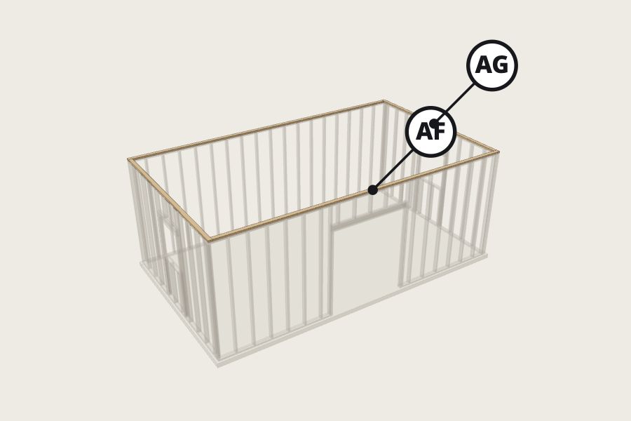
Lap the cap plates
AF ×2 2x4 284-1/2"AG ×2 2x4 164-1/2"
- Cap plates overlap every corner. That ties the walls into one box.
- Nails every 16", two at each lap.
hammer
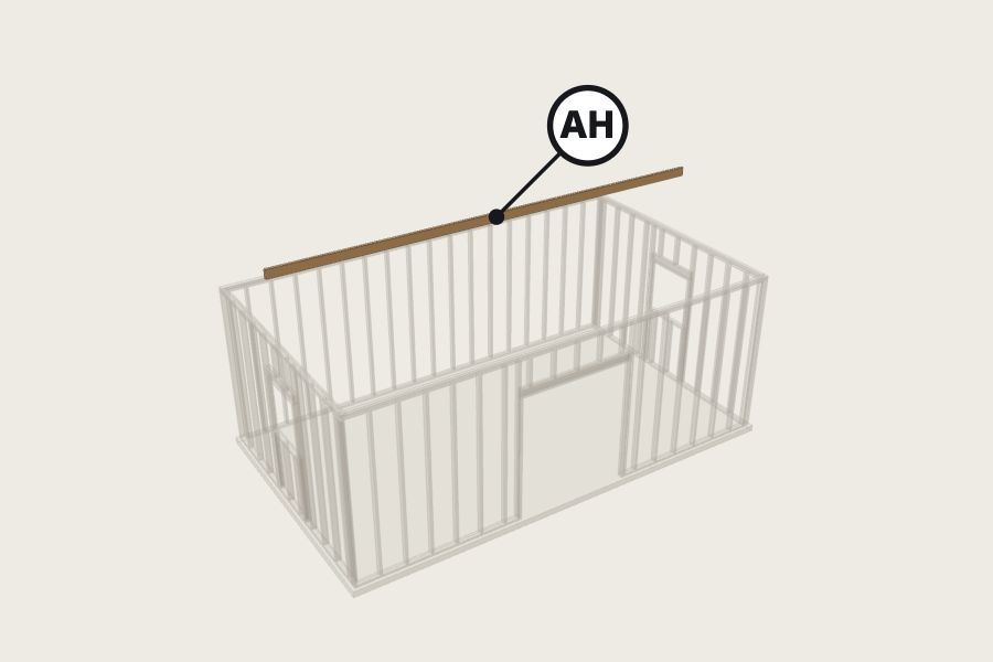
Raise the ridge
AH ×1 2x6 288"
- Ridge AH on temporary posts at the height shown.
- Plumb and brace before any rafters.
levelclamps
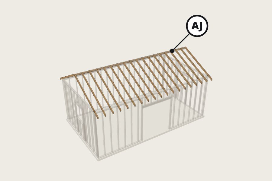
Set the rafters
AJ ×38 2x4 108-1/4"
- Cut ONE pattern rafter. Check it in three places. Then cut the rest.
- Every 16", over the studs.
- Hurricane tie every rafter to the plate.
speed squaresawdrill
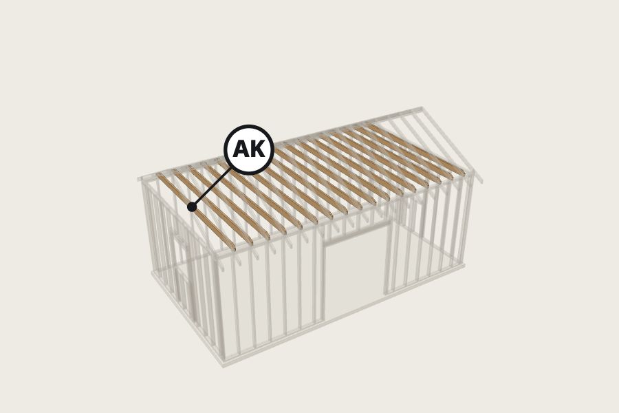
Tie the rafters
AK ×17 2x6 168"
- A tie beside every rafter pair, on the cap plates.
- Nail each end to its rafter.
hammer
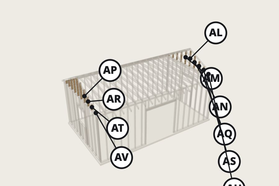
Fill the gable ends
AL ×2 2x4 39-5/8"AM ×2 2x4 35-5/8"AN ×2 2x4 31-5/8"AP ×2 2x4 27-5/8"AQ ×2 2x4 23-5/8"AR ×2 2x4 19-5/8"AS ×2 2x4 15-5/8"AT ×2 2x4 11-5/8"AU ×2 2x4 7-5/8"AV ×2 2x4 3-5/8"
- Studs every 16" from the cap up to the rafter.
- Measure each in place. Long point up.
speed squaresaw
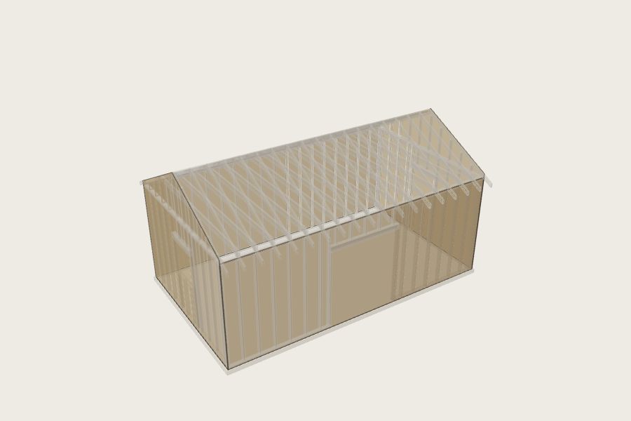
Sheath the walls
- Sheets vertical, edges on studs, 1/8" gaps.
- Nails 6" on edges, 12" in the middle. Cut out the openings after.
sawnailerchalk line
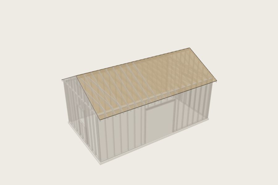
Sheath the roof
- Long edge across the rafters, H-clips between, rows staggered.
- Drip edge, underlayment, drip edge, shingles.
sawnailer
The proof
Every member was sized by calculation, and the 3D model was tested piece against piece. These are the results for this plan.
✓ No two pieces occupy the same space
All 183 pieces tested pairwise as exact solids (mitres, birdsmouths, cheek cuts, notched stringers): no overlap deeper than 1/50".
✓ Every piece is connected to the ground
All 184 pieces trace a chain of contact down to the foundation.
✓ Rafters 2x4 58% used
2x4 SPF #2, span 6.94 ft, w = 43 plf total / 28 plf live
Bending: M = wL²/8 = 3098 in·lb → fb = M/S = 1011 psi ≤ F'b = 1736 psi  (58% used)
Shear: fv = 1.5V/A = 43 psi ≤ F'v = 155 psi  (27% used)
Deflection: 5wL⁴/384EI = 0.194" ≤ L/240 = 0.347"  (56% used)
✓ Header over door (front) 2x6 80% used
2-ply 2x6 SPF #2, span 6.42 ft, w = 257 plf total / 168 plf live
Bending: M = wL²/8 = 15900 in·lb → fb = M/S = 1051 psi ≤ F'b = 1308 psi  (80% used)
Shear: fv = 1.5V/A = 75 psi ≤ F'v = 155 psi  (48% used)
Deflection: 5wL⁴/384EI = 0.110" ≤ L/240 = 0.321"  (34% used)
✓ Studs (front wall) 60% used
2x4 SPF #2, unbraced length 104.6" (le/d = 29.9 ≤ 50)
F*c = 1521 psi, FcE = 0.822·Emin/(le/d)² = 469 psi → Cp = 0.286
Capacity = Cp·F*c·A = 2281 lb ≥ load 343 lb  (15% used)
✓ Header over window (right) 2x6 1% used
2-ply 2x6 SPF #2, span 3.29 ft, w = 6 plf total / 4 plf live
Bending: M = wL²/8 = 98 in·lb → fb = M/S = 6 psi ≤ F'b = 1308 psi  (0% used)
Shear: fv = 1.5V/A = 1 psi ≤ F'v = 155 psi  (1% used)
Deflection: 5wL⁴/384EI = 0.000" ≤ L/240 = 0.165"  (0% used)
✓ Studs (back wall) 60% used
2x4 SPF #2, unbraced length 104.6" (le/d = 29.9 ≤ 50)
F*c = 1521 psi, FcE = 0.822·Emin/(le/d)² = 469 psi → Cp = 0.286
Capacity = Cp·F*c·A = 2281 lb ≥ load 343 lb  (15% used)
✓ Header over window (left) 2x6 1% used
2-ply 2x6 SPF #2, span 3.29 ft, w = 6 plf total / 4 plf live
Bending: M = wL²/8 = 98 in·lb → fb = M/S = 6 psi ≤ F'b = 1308 psi  (0% used)
Shear: fv = 1.5V/A = 1 psi ≤ F'v = 155 psi  (1% used)
Deflection: 5wL⁴/384EI = 0.000" ≤ L/240 = 0.165"  (0% used)
✓ Birdsmouth notch shear (rafters) 2x4 60% used
Heel cut 3/4" plumb leaves dn = 2.83" of the 3.5" depth over the bearing.
NDS 3.4.3.2 notched end: V'r = 2/3 · F'v · b · dn · (dn/d)² = 287 lb ≥ reaction 172 lb (60% used)
Roof: 10 psf dead + snow 0.7 × 30 = 21 psf. Rafter ties at every rafter pair stop the walls spreading (a ridge board is not a beam). Nail per IRC Table R802.5.2.
Questions
How much lumber does a 14x24 Workshop need?
17 2x4 × 8′, 95 2x4 × 10′, 4 2x4 × 14′, 4 2x4 × 20′, 4 2x6 × 8′, 17 2x6 × 16′, 1 2x6 × 20′, 2 PT 2x4 × 10′, 2 PT 2x4 × 14′, 1 PT 2x4 × 20′. 26 7/16" OSB wall sheathing, 4×8 (10% waste); 16 1/2" OSB roof sheathing, 4×8 (15% waste); 15 bundles shingles (4.3 squares + 10%).
What size rafters does a 14x24 Workshop need?
2x4 at 16″ on center, using 58% of their capacity at 30 psf ground snow. The bending, shear and deflection numbers are in the proof section.
How tall is it?
12′ 10-7/8″ at the peak, measured from the ground.
Do I need a permit for a 14x24 Workshop?
It covers 336 sq ft. The model code (IRC R105.2) exempts one-story detached accessory buildings up to 200 sq ft, and many towns set the line at 120 sq ft. Call your building department before you dig.
Can I change the size or add a door?
Yes. Open the plan in the builder, change any number, and the cuts, shopping list and checks update instantly.
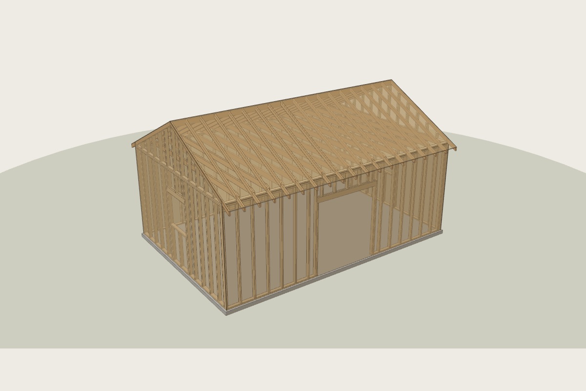 16×24 Workshop
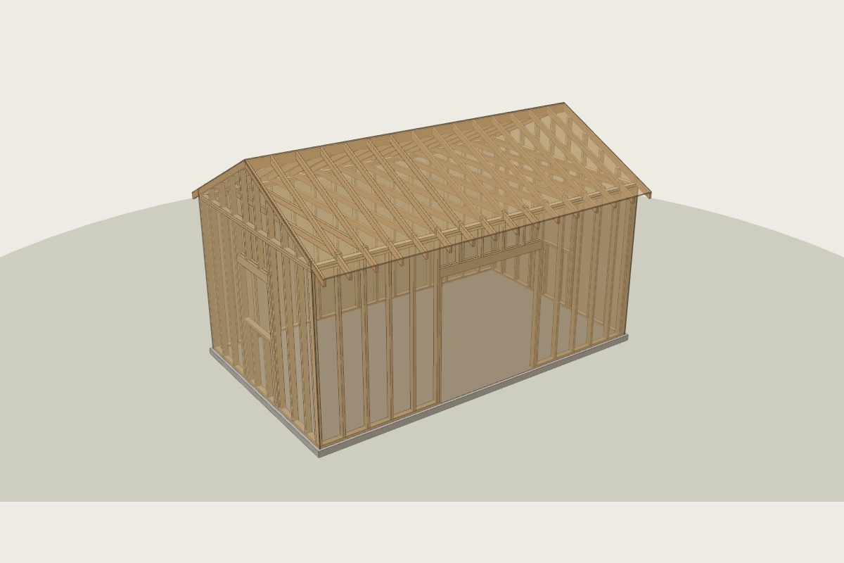 12×20 Workshop
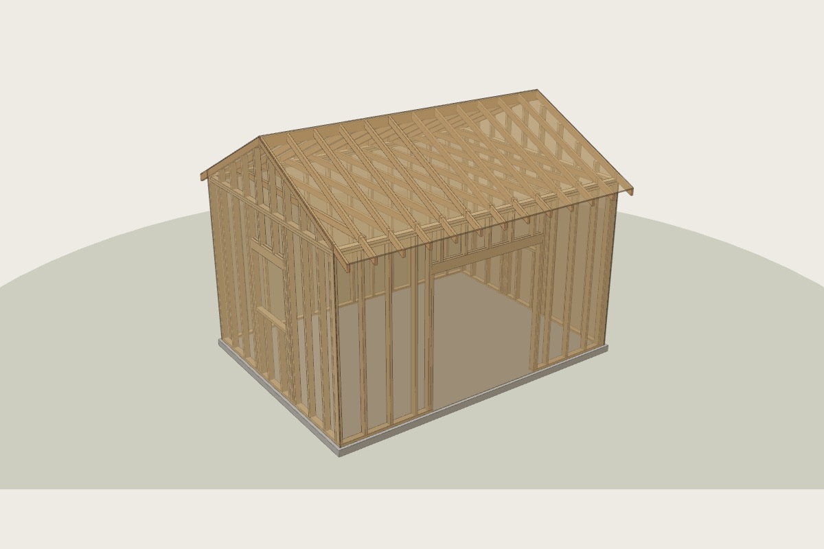 12×16 Workshop